Cisco - Guide to configuring EtherChannels
One of many useful concepts to understand in networking is the use of EtherChannels, how to configure them and when to use them.
Simply put, an EtherChannel provides redundancy, increase in bandwidth, and load-balancing data streams across the different links. At Layer 2 it also provides better performance with Spanning-Tree Protocol [STP], which I will provide an example for later in this tutorial.
Main difference you need to know between Layer 2 and Layer 3 EtherChannels is the following:
- In Layer 2, you bundle trunk ports and prevent STP blocking ports. Access ports can also be configured as long as they are on the same VLAN [the native VLAN].
- In Layer 3, you bundle routed ports. Usually used to connect L3 switches to routers, in order to achieve higher throughput in service provider networks. I don’t currently work there, so I cannot say much more than this.
I will provide you the simple configuration steps and the statistics that we humans love. . .

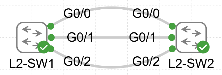
I have set up two switches and will proceed with connecting their physical interfaces together.

For this example we have connected 3 links between the two switches, let me walk you through the configuration steps in bundling the three interfaces together. Lets start by configuring L2-SW1:
L2-SW1#configure terminal
L2-SW1(config)#int range g0/0-2
L2-SW1(config-if-range)#channel-group 1 mode active
Channel-group is followed by an identification number of your choosing, from 1 to 255, and then the mode, in the above case being set to active. For the mode there are three options to choose from, two of the options are using a negotiation protocol, and one of them is for static configuration.
Following are the options:
- LACP or Link Aggregation Control Protocol, is an IEEE open standard, used to communicate in mixed vendor environments. This is the preferred choice for configuring L2 EtherChannels.
- PAgP or Port Aggregation Protocol, is Cisco proprietary, and used to communicate between Cisco devices only.
- "on” for static EtherChannel configuration, without the negotiation part provided by the above two protocols.
LACP has two negotiation states, Active and Passive:
- Active, works with active and passive on the other side.
- Passive, works only with active on the other side.
PAgP has also two negotiation states, named Desirable and Auto:
- Desirable, works with desirable or auto on the other side.
- Auto, works only with desirable on the other side.
EtherChannel has only one “non-negotiable” state:
- on [it does not care about your feelings, you better have set the same mode on the other side, being on]
LACP and PAgP protocols negotiate link states, whether up or down, and you have to make sure states on each side work with each other. You can check this with the negotiation states mentioned above.
If you want to configure an EtherChannel on each side to always be on, in other words static configuration, without needing to communicate whether a link is down or up, then you will set both sides of the channel-group with mode on.
However for most scenarios and something I would also recommend, is to use LACP with the mode on each side set to active. Simply because its an open standard supported by most vendors, and in this world we have physical stuff that can fail and therefore the channel-group needs to negotiate for this event and react accordingly, such as by stopping the sending of data on that failed member link within the channel-group.
Now with the protocols aside, lets continue with the configuration. In the previous steps we have added the three links to the channel-group 1 with mode active, meaning we are using LACP and actively are trying to negotiate a link to come up on each side. At this stage I want you to see the three links as a single logical link or port, also known as a port channel, to which we will configure it to act as a trunk with a native VLAN of 10. In this case you could also set the port-channel to be an access port, but I prefer wearing trunks, that is a bad pun indeed, lets continue with the configuration.
L2-SW1#configure terminal
L2-SW1(config)#vlan 10
L2-SW1(config-vlan)#exit
L2-SW1(config)#interface port-channel 1
L2-SW1(config-if)#switchport trunk encapsulation dot1q (802.1q for VLAN tagging)
L2-SW1(config-if)#switchport mode trunk
L2-SW1(config-if)#switchport trunk native vlan 10
Now I will configure the other switch with same configuration from the start:
L2-SW2#conf terminal
L2-SW2(config)#interface range g0/0-2
L2-SW2(config-if-range)#channel-group 1 mode active
L2-SW2(config-if-range)#exit
L2-SW2(config)#vlan 10
L2-SW2(config-vlan)#exit
L2-SW2(config)#interface port-channel 1
L2-SW2(config-if)#switchport trunk encapsulation dot1q
L2-SW2(config-if)#switchport mode trunk
L2-SW2(config-if)#switchport trunk native vlan 10
L2-SW2(config-if)#end
You can use the “show interface port-channel 1” command like you would with any other interface.
L2-SW2#show int port-channel 1
Port-channel1 is up, line protocol is up (connected)
Hardware is EtherChannel, address is 5254.0006.ab49 (bia 5254.0006.ab49)
MTU 1500 bytes, BW 3000000 Kbit/sec, DLY 10 usec, reliability 255/255, txload 1/255, rxload 1/255 ...
As you can see the interface is correctly identified as an EtherChannel with the Bandwidth [BW] of 3 Gigabits, which is the three Gigabit links that we bundled together. Another very useful command is the “show etherchannel summary”:
L2-SW2#show etherchannel summary
Flags:  D - down | P - bundled in port-channel
I - stand-alone | s - suspended
H - Hot-standby (LACP only)
R - Layer3 | S - Layer2
U - in use | N - not in use, no aggregation
f - failed to allocate aggregator

M - not in use, minimum links not met
m - not in use, port not aggregated due to minimum links not met
u - unsuitable for bundling
w - waiting to be aggregated
d - default port

A - formed by Auto LAG


Number of channel-groups in use: 1
Number of aggregators:           1
Group  Port-channel  Protocol    Ports
------+-------------+-----------+-----------------------------------------------
1      Po1(SU)         LACP      Gi0/0(P)    Gi0/1(P)    Gi0/2(P)
We can see by the codes that our created Port-Channel 1 is Layer 2 and In-Use I always like to double check this with simple display of Up & Up with “show ip interface brief” command.
L2-SW2#show ip interface brief
Interface IP-Address OK? Method Status Protocol
GigabitEthernet0/0 unassigned YES unset up up
GigabitEthernet0/1 unassigned YES unset up up
GigabitEthernet0/2 unassigned YES unset up up
Port-channel1 unassigned YES unset up up
Now whilst the above looks all good, I like to give it a real world test of connectivity with ping command. Since this is a Layer 2 setup, no IPv4 addresses have been configured, so lets follow the native VLAN of the trunks [being 10] and create the VLAN interfaces on each switch, which will then be used for pinging each other for science.
L2-SW1#conf t
L2-SW1(config)#int vlan 10
L2-SW1(config-if)#ip address 192.168.0.1 255.255.255.0
L2-SW1(config-if)#no shut
L2-SW1(config-if)#end
L2-SW1#wr
L2-SW2#conf t
L2-SW2(config)#int vlan 10
L2-SW2(config-if)#ip address 192.168.0.2 255.255.255.0
L2-SW2(config-if)#no shut
L2-SW2(config-if)#end
L2-SW2#wr
L2-SW1#ping 192.168.0.2
Type escape sequence to abort.
Sending 5, 100-byte ICMP Echos to 192.168.0.2, timeout is 2 seconds:
!!!!!
Success rate is 100 percent (5/5), round-trip min/avg/max = 1/1/2 ms
L2-SW2#ping 192.168.0.1
Type escape sequence to abort.
Sending 5, 100-byte ICMP Echos to 192.168.0.1, timeout is 2 seconds:
.!!!!
Success rate is 80 percent (4/5), round-trip min/avg/max = 2/4/7 ms
Brilliant, both of the pings are successful and at this point you have a functioning layer 2 EtherChannel.
What the Spanning-Tree! Lets see the usefullness of a L2 EtherChannel
Now as promised let me provide you an example of “using VS not using” EtherChannel and what difference it provides with STP running at Layer 2.

We still have the same setup of two switches and three links between them, acting as one logical link. Lets start with the port-channel configuration we have just achieved and see what spanning-tree output provides by using the following command “show spanning-tree vlan 10”
L2-SW1#show spanning-tree vlan 10

VLAN0010
  Spanning tree enabled protocol ieee
Root ID Priority 32778
Address 5254.0005.59ba
This bridge is the root
Hello Time 2 sec  Max Age 20 sec  Forward Delay 15 sec

Bridge ID Priority 32778 (priority 32768 sys-id-ext 10)
 Address 5254.0005.59ba
Hello Time 2 sec  Max Age 20 sec  Forward Delay 15 sec
Aging Time  300 sec

Interface  Role  Sts  Cost  Prio.Nbr Type
------------------- ---- --- --------- -------- --------------------------------
Po1  Desg  FWD  3  128.65  P2p
Pay attention to the Po1 [port-channel] interface, as it has the role of being a Designated port and is in Forwarding state. The interface contains a bundle of three ports which allow all of them to be active in data transmission. This is because STP can only see the port-channel as a single logical link, and this cannot cause a loop between the two switches.
Let me revert back the configuration to the three ports being separate, without port-channel setup, and then look at the output of STP on both of the switches. Lets start with SW1:
VLAN0010
Spanning tree enabled protocol ieee
Root ID Priority 32778
Address 5254.0005.59ba
This bridge is the root
Hello Time 2 sec  Max Age 20 sec  Forward Delay 15 sec

Bridge ID Priority 32778 (priority 32768 sys-id-ext 10)
             Address     5254.0005.59ba
Hello Time   2 sec  Max Age 20 sec  Forward Delay 15 sec
Aging Time  300 sec
Interface  Role  Sts  Cost  Prio.Nbr Type
------------------- ---- --- --------- -------- --------------------------------
Gi0/0   Desg FWD  4  128.1  P2p
Gi0/1   Desg FWD  4  128.2  P2p
Gi0/2   Desg FWD  4  128.3  P2p
Don’t get confused by the output, the three links are only in forwarding state on this switch because SW1 is chosen to act as the root bridge for VLAN 10 in STP, because of its lower system ID. Now lets look at the non-root bridge, being SW2:
VLAN0010
Spanning tree enabled protocol ieee
Root ID Priority 32778
Address 5254.0005.59ba
Cost 4
Port 1 (GigabitEthernet0/0)
Hello Time 2 sec  Max Age 20 sec  Forward Delay 15 sec

Bridge ID  Priority 32778  (priority 32768 sys-id-ext 10)
Address 5254.001b.11a7
Hello Time 2 sec  Max Age 20 sec  Forward Delay 15 sec
Aging Time 300 sec

Interface   Role  Sts  Cost  Prio.Nbr Type
------------------- ---- --- --------- -------- --------------------------------
Gi0/0   Root FWD  4  128.1  P2p
Gi0/1   Altn BLK  4  128.2  P2p
Gi0/2   Altn BLK  4  128.3  P2p
Since SW2 is not a root-bridge for VLAN 10, only one port is in forwarding state, with the other two in blocking state. The forwarding port is the only one that will forward all data, whereas the two blocking ones can only forward and receive the needed data, which are the BPDUs (Bridge Protocol Data Units) that switches use to communicate with each other.
So with EtherChannel set up using a bundle of links between the two switches, we can create a single logical link for STP, with three times the bandwidth, redundancy and load-balancing. In order to get proper load-balancing it does require extra configuration which would need a topic of its own.
Configuring EtherChannel on layer 3 switch
We are now at the last part of this tutorial, keeping it simple, EtherChannel setup at this layer allows us to use routing, meaning STP does not take place at this layer and therefore we can skip the details of that.
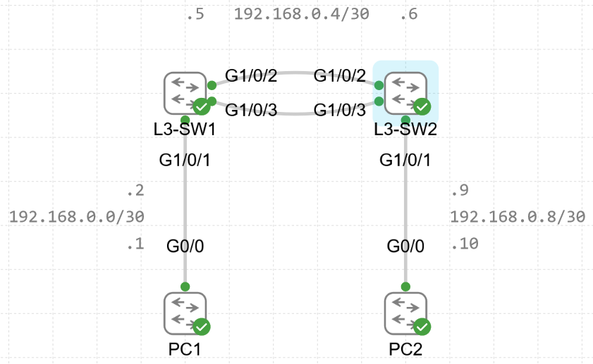
For this setup we are going to use two L3 Catalyst 9000 series switches, and two other switches to act as end hosts that we will use for testing the routing once set up. Since they are L2 switches, an IPv4 address will be assigned on their VLAN 1 interface and default route towards their connected L3 switch interface. We will use /30 subnets between the switches, as that will provide two usable hosts per subnet for the links.

On a layer 3 switch, in order to configure an IP address on a physical interface, you need to disable the switching functionality of that port. This will turn it into a routed port, which disables the need to use STP. Lets start by configuring the routed port on the L3 switch:
L3-SW2(config)#int g1/0/1
L3-SW2(config-if)#no switchport
L3-SW2(config-if)#ip address 192.168.0.9 255.255.255.252
Configuring a L3 EtherChannel is the same as L2, except you will add an IP address to the port-channel instead of configuring the switchport as trunk or access. Lets proceed with configuring the L3-SW1 and L3-SW2 switches:
L3-SW1#conf t
L3-SW1(config)#int range g1/0/2-3
L3-SW1(config-if-range)#no switchport
L3-SW1(config-if-range)#channel-group 1 mode active
L3-SW1(config-if-range)#exit
L3-SW1(config)#int port-channel 1
L3-SW1(config-if)#no switchport
L3-SW1(config-if)#ip address 192.168.0.5 255.255.255.252
L3-SW1(config-if)#no shut
L3-SW2#conf t
L3-SW2(config)#int range g1/0/2-3
L3-SW2(config-if-range)#no switchport
L3-SW2(config-if-range)#channel-group 1 mode active
L3-SW2(config-if-range)#exit
L3-SW2(config)#int port-channel 1
L3-SW2(config-if)#no switchport
L3-SW2(config-if)#ip address 192.168.0.6 255.255.255.252
L3-SW2(config-if)#no shut
We have now configured layer 3 EtherChannel on both of the switches, lets confirm this by running “show etherchannel summary” command.
L3-SW2#show etherchannel summary
Flags: D - down | P - bundled in port-channel
I - stand-alone | s - suspended
H - Hot-standby (LACP only)
R - Layer3 | S - Layer2
U - in use | f - failed to allocate aggregator

M - not in use, minimum links not met
u - unsuitable for bundling
w - waiting to be aggregated
d - default port

A - formed by Auto LAG


Number of channel-groups in use: 1
Number of aggregators: 1

Group   Port-channel   Protocol   Ports
------+-------------+-----------+-----------------------------------------------
1   Po1(RU)   LACP  Gi1/0/2(P)  Gi1/0/3(P)
This has confirmed it has been configured correctly, both switches show the same thing of using R and U codes, R for it being a Layer3 EtherChannel and U for it being In-Use, great! Now before finishing this off we have to test the functionality. With this being a L3 setup we need to have routing configured. I will use RIPv2 since its quick and simple to set up for this example, if you want to know more about RIP I will leave a link to it at the end of the page.
L3-SW1#conf t
L3-SW1(config)#ip Routing
L3-SW1(config)#router rip
L3-SW1(config-router)#version 2
L3-SW1(config-router)#no auto-summary
L3-SW1(config-router)#network 192.168.0.4
L3-SW1(config-router)#end
L3-SW1(config-router)#wr
Now just repeat the commands on SW2, and you will have now set up RIPv2 between the switches so they can start sharing routes. We can confirm we are learning routes by using “show ip route” command:
L3-SW1#show ip route
… R – RIP ...
192.168.0.0/24 is variably subnetted, 5 subnets, 2 masks
C  192.168.0.0/30 is directly connected, GigabitEthernet1/0/1
L  192.168.0.2/32 is directly connected, GigabitEthernet1/0/1
C  192.168.0.4/30 is directly connected, Port-channel1
L  192.168.0.5/32 is directly connected, Port-channel1
R  192.168.0.8/30 [120/1] via 192.168.0.6, 00:00:22, Port-channel1
As you can see there is a route learned by RIP of the subnet between SW2 and PC2, and if we look at SW2 output, we can see the same thing happening where subnet between SW1 and PC1 has been learned.
L3-SW2#show ip route
… R – RIP ...
   192.168.0.0/24 is variably subnetted, 5 subnets, 2 masks
R  192.168.0.0/30 [120/1] via 192.168.0.5, 00:00:02, Port-channel1
C  192.168.0.4/30 is directly connected, Port-channel1
L  192.168.0.6/32 is directly connected, Port-channel1
C  192.168.0.8/30 is directly connected, GigabitEthernet1/0/1
L  192.168.0.9/32 is directly connected, GigabitEthernet1/0/1

By this point you have configured the layer 3 EtherChannel and configured RIPv2 routing protocol! Finally, the last thing left to do is to test the connectivity from PC1 to PC2, which will overall confirm that the EtherChannel and routing protocol are working correctly.
PC1#traceroute 192.168.0.10 (IPv4 address of PC2)
Type escape sequence to abort.
Tracing the route to 192.168.0.10
VRF info: (vrf in name/id, vrf out name/id)
  1 192.168.0.2 54 msec 48 msec 52 msec
  2 192.168.0.6 143 msec 82 msec 76 msec
  3 192.168.0.10 96 msec 76 msec *